
Check the WIRE board. Take off the WCN30connector,press [WIRE FEED] button, check Pin1 & 2 of WCN30 and screen voltage meter,
-Pin1 & 2 and screen can get DC7~10 voltage. It mean PCB(WIRE, WPG,IOboard) function is well.
Check the hardware from the WCN30 cable to the upper head.
Please check as A step.
-Pin1 & 2 there is not voltage, the screen there is DC7~10 voltage. Itmean the WIRE board was damaged.
Please check as B step.
-Pin1& 2and screen can not get any voltage. It mean PCB(WIRE, WPG, IO board) function is not well.
Please check as C step.A Step
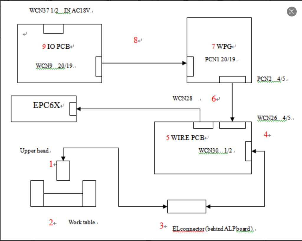
- Check out position 3(see drawing), unplug the ELconnectors, press wire feed button and would be DC7~10 voltage.
- Press [WIRE FEED]button, check if there is voltage of meter, and test gap voltage between upper head and work table by multi meter, it should be DC7~10 voltage. If so but no gap voltage, please check out power contact or try to adjust the position. Please follow nextstep, if there is still no gap voltage.
- For AWT machine, check it is locked with power contact base. It is should be move smoothly when pull power contact base.
- Check out position 4 (see drawing), measuring Pin 1 and 2 of WCN30 during wire feeding, it would be DC7~10 voltage.
B Step
- Check fuse 6 of WIRE PCB, if it is broken?
- Replace WIRE board.
C Step
- Check I/O PCB, measuring pin1 and 2 of WCN 37. It should beAC18voltage. If yes, please follow next step.
- Check I/O PCB, measuring pin19and 20of WCN9. It should be DC7~10voltage. If not, replace IO board. If yes, please follow next step.
- Check WPGPCB, measuring pin19and 20of PCN1and pin4 and 5 of PCN2. It should be DC7~10 voltage. If not, replace WPGboard
Следует заметить, что производителем допускается модификация конечного участка проводки к верхней голове и рабочему столу согласно ниже приведенной схеме:
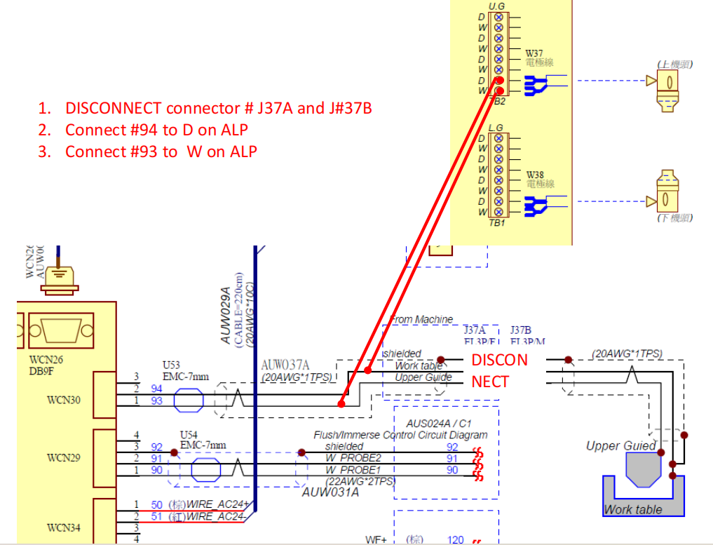
Это может быть оправдано на практике в случае повреждения штатного участка этой проводки.
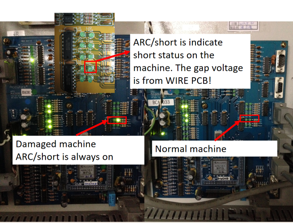
Дополнительная информация — при коротком замыкании загорается светодиод L20 на WPG BOARD:
Отдельные материалы по теме: